Sept. 9, 2002 RadioAnarchy
RadioAnarchy RadioAnarchy radio radio Radio Anarchy anarchy anarchy transmitter
schematic schematic shortwave shortwave
RADIO ANARCHY

The Parts List for the Shortwave Transmitter:
(update 02/26/02 - a snubber network needs to be put on
the
primary side of T2. Check back soon for details. A
100 ohm
resistor in series with a 100 PF capacitor should work.)
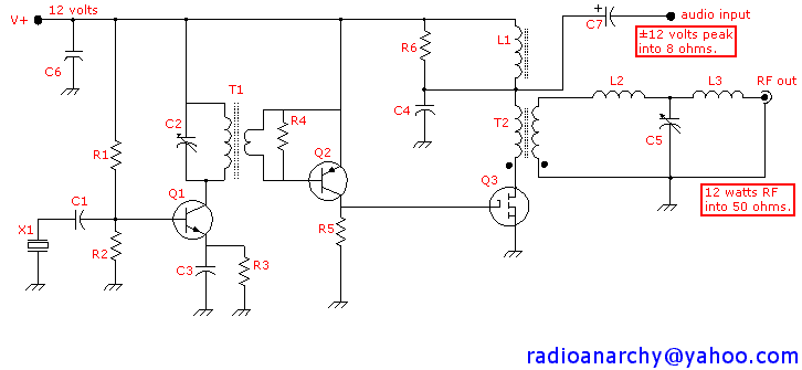
- R1 - 33K ohms, ¼ watt, carbon.
- R2 - 4.7K
- R3, R6 - 100
- R4 - 10
- R5 - 100, 1 watt, or greater.
- C1 - 47 to 470pF, or greater, silver mica or disc ceramic.
Better yet,
a trimmer capacitor, to slightly change
frequency ±1 KHZ.
- C2 - 10 to 140 pF trimmer.
- C3 - 100 to 220 pF, silver mica or disc ceramic.
- C4 - .01 to .05 µF.
- C5 - 300 - 800 pF, or (? ? ?) variable capacitor. I used an
Arco
TC-4610 (260-900 pF) compression trimmer.
- C6 - .01 to .1 µF.
- C7 - 1000 µF or greater, electrolytic, 25 volts or greater.
- X1 - Fundamental mode crystal, 5 to 8 MHz.
- T1 - On an Amidon T50-2 toroid core, primary is 26 turns of
#28 magnet
wire closewound, secondary is 2 turns
wound over the primary windings.
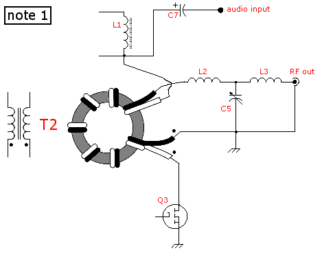
- T2 - On an Amidon T50-2 toroid core, bifilar wind 6 to 8 turns
of #18
magnet wire. See note 1 for details.
- L1 - 2 mH or greater, .5 ohm or less resistance. I used
the
inductor from Radio Shack p/n 270-0030A HD Noise Filter.
One could
also use the 4 or 8 ohm secondary of a medium
sized audio transformer, or
the secondary side (6 to 24 volts)
of an AC mains power transformer.
- L2 - .7 µH. Wind 7 turns of #16 magnet wire on a 5/8
inch
diameter form, then remove form.
- L3 - 1.4 µH. Wind 11 turns of #16 magnet wire on a 5/8
inch
diameter form, then remove form.
- Q1 - 2N2222
- Q2 - 2N2907
- Q3 - IRF510 or IRF511 (Radio Shack p/n 276-2072A)

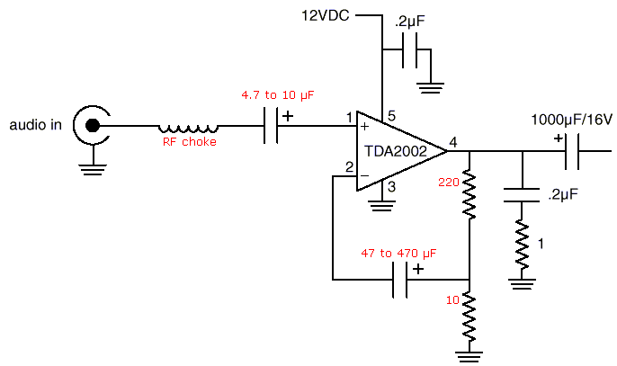
Grenade audio section modification:


